|
Weber 40 45 DCOE |
|
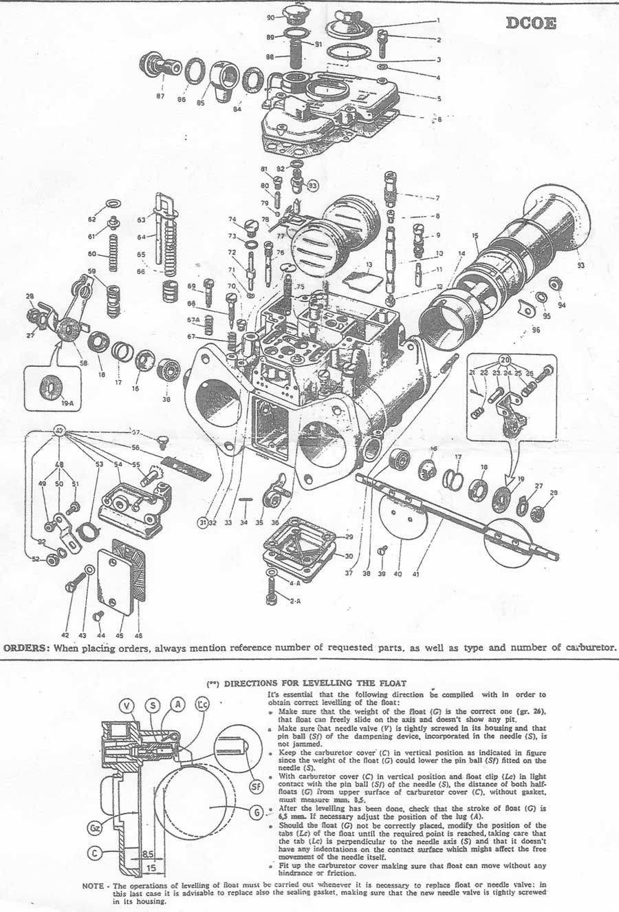
This carb is synonymous with performance and almost as good as fuel injection in its time. The carburettor is fully customisable with all the jets and venturi's able to be changed to suit whatever application you have in mind. I found a DCOE Weber Instruction Manual that goes in deep. Deeper than I have ever gone as I did not have the special tools. I found this helpful article from Redline Performance. Recommended Jetting Guide for fitting Webers to popular old cars.
|
|||||||||||||||||||||||||||||||||||||||||||||||||||||||||||||||||||||||||||||||||||||||||||||||||||||||||||||||||||||||||||||||||||||||||||||||||||||||||||||||||||||||||||||
|
|
|||||||||||||||||||||||||||||||||||||||||||||||||||||||||||||||||||||||||||||||||||||||||||||||||||||||||||||||||||||||||||||||||||||||||||||||||||||||||||||||||||||||||||||
Below is an alternate kit I used on a 40DCOE. On close examination you will see several differences between the schematic above and the one below as well as different float level specs. The most obvious is the aux venturi differences. I used the below procedure when I re-kitted this 40 DCOE. Please do not e-mail asking which one should be used. I would choose the lower setting and if it is found to be delivering fuel late, then raise the float level to the dimension on the top schematic.
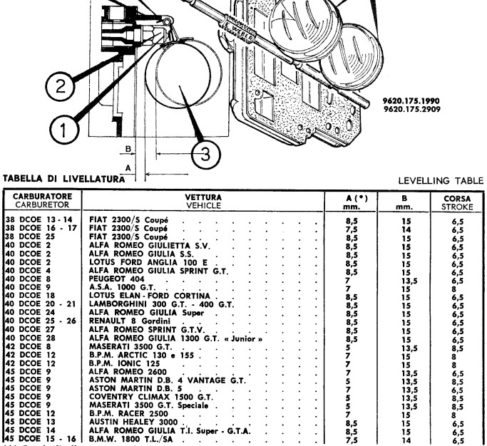
I simply do not have the correct schematic of this 40DCOE that I put a kit through. I found some float level specs inside the DCOE Weber Instruction Manual (link to the manual at the top) and as luck would have it the spec for this Weber was 8.0mm with gasket on with a 15mm drop. The correct float level setting also depends on the angle the carby is fitted. Some are fitted flat while others may be at a 5-10 deg angle. These two cases would require different float level settings. As you can see in the table below that there are four different float level settings listed when these were fitted by factory. Each vehicle had differing specs. Confusing right, because DCOE's are fitted aftermarket, choosing a float level can be daunting. I would start at 8.5mm with a 13.5mm drop. If the main jet circuit starts late then raise the float level. It is not to difficult to take the top off and readjust. This is of course dependant on the correct choke & aux venturis being fitted as well as emulsion tubes. All of these contribute to fuel delivery at the correct time.
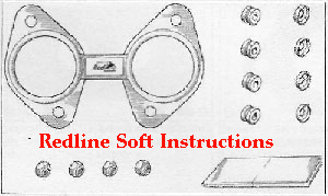
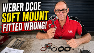
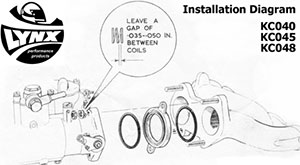
Soft mounts may also be required on a Weber aftermarket installation. I have included the fitting instructions below for the two most popular soft mount brands. It is very important that soft mounts are fitted correctly, if their too tight, then you may as well use normal base gaskets because the benefit provided to the installation will be zero. Too loose and they will leak vacuum. View the video below to get what I mean.
|